1. B 935 Valvole a doppia sede di fondo Double seat valves
2. 2 CERTIFICAZIONI CERTIFICATIONS DATI TECNICI B 935 TECHNICAL DETAILS STRUTTURA VALVOLA Connessioni da DN40 a DN150 DIN, SMS, IDF, BS (RJT), Clamp, Flangia Altre connessioni a richiesta Materiale a contatto con il prodotto AISI 316L (1.4404) Altro materiale a richiesta Materiale guarnizioni a contatto con il prodotto (omologazione FDA) EPDM, FKM, HNBR. Altro materiale a richiesta Temperatura massima prodotto (EPDM applicazioni con aria) 140 °C (284 °F) Per temperature diverse contattare Bardiani Valvole Temperatura minima prodotto (EPDM applicazioni con aria) -10 °C (14 °F) Pressione massima prodotto 10 bar (145 psi) Pressione massima di tenuta Vedi tabella Finitura superficiale materiale a contatto con il prodotto Ra 0,8 μm (altri tipi di finitura a richiesta) Connessioni barriera vapore attacchi 1/8” (BSP) STRUTTURA ATTUATORE PNEUMATICO Attacchi aria 1/8” (BSP) per tubo 6 x 4 mm Pressione Da 6 bar (87 psi) a 8 bar (116 psi) Materiale cilindro AISI 304 (1.4301) Materiale guarnizioni NBR SI CONSIGLIA L’APPLICAZIONE IN VERTICALE VALVE STRUCTURE Connections from DN40 to DN150 DIN, SMS, IDF, BS (RJT), Clamp, Flange Other connections on request Material in contact with the product AISI 316L (1.4404) Other material on request Material gaskets in contact with the product (FDA homologation) EPDM, FKM, HNBR. Other material on request Max. product temperature (EPDM applications with air) 140 °C (284 °F) For other temperature, please ask Bardiani Valvole Min. product temperature (EPDM applications with air) -10 °C (14 °F) Max. product pressure 10 bar (145 psi) Max. working pressure See table Finish on surfaces in contact with the product Ra 0.8 μm (other types of surface finish on request). Connection steam barrier connectors 1/8” (BSP) PNEUMATIC ACTUATOR STRUCTURE Air connectors 1/8” (BSP) for pipe 6 x 4 mm Air pressure From 6 bar (87 psi) to 8 bar (116 psi) Cylinder material AISI 304 (1.4301) Gasket material NBR VERTICAL FITTING IS ADVISABLE
5. 5 CONFIGURAZIONI CORPI VALVOLA VALVE BODIES CONFIGURATIONS B 935 Chiusa Aperta Closed Open CONFIGURAZIONI CORPI VALVOLA SENZA FLANGIA SU 1° ATTACCO ( SU RICHIESTA ) VALVE BODIES CONFIGURATIONS WITHOUT 1ST PORT FLANGED (ON REQUEST) CONFIGURAZIONI CORPI VALVOLA CON FLANGIA SU 1° ATTACCO VALVE BODIES CONFIGURATIONS WITH 1ST PORT FLANGED CONFIGURAZIONI CORPI ORIENTABILI ORIENTABLE VALVE BODIES CONFIGURATIONS 1°- 2°- 3° .... esempi di lettura per attacchi con tipi e/o dimensioni diverse 1st - 2nd - 3rd .... examples for reading ends connections with different types and/or dimensions 1 “L” 2 “T” V45° 1 “L” 2 “T” 1 “LL” 2 “LT” 3 “TL” 4 “TT” 1° 2° 3° 1° 2° 3° 4° Chiusa Aperta Closed Open 2 “T” Flangia / Femmina / Saldare 2 “T” Flange / Male / Weld 1 “LL” Femmina / Saldare 1 “LT” Male / Weld 1° 2° 3° 1° 2° DN50 DN50 DN65 (DN > A QUELLO RICHIESTO) DN65 (DN > REQUESTED) DN50
4. 4 CORPI VALVOLA DI DIVERSE DIMENSIONI Per ogni diametro indicato nella tabella delle dimensioni, è possibile ottenere su richiesta corpi valvola con attacchi di diametro diverso. VALVE BODIES WITH DIFFERENT SIZES It is possible to supply bodies with ports of a different diameter from the standard. ESECUZIONI SPECIALI SU RICHIESTA Ogni accessorio è disponibile su richiesta del cliente per tutti i diametri e tutte le configurazioni corpi valvola. È inoltre possibile la personalizzazione di attacchi, diametri oppure soluzioni non presenti a catalogo. Bardiani Valvole consiglia di consultare sempre l’ufficio tecnico in fase d’ordine per ulteriori informazioni e studi di fattibilità. SPECIAL OPTIONS AND VARIATION ON REQUEST On request all accessories are available for all sizes of valve and body configurations. Additionally special ports, diameters and other tailor-made solutions are available. Bardiani Valvole can also provide technical support, advice and feasibility analysis for other requests. B 935 SOLUZIONI VARIE DIFFERENT SOLUTIONS DIN DN INCHES DN P1 bar / psi P2 bar / psi 40 1”1/2 3.2 / 46 10 /145 50 2” 3.2 / 46 10 / 145 65 2” 1/2 2.8 / 41 10 / 145 80 3” 2 / 29 10 / 145 100 4” 3 / 43 10 / 145 125 2.7 / 39 10 / 145 150 2.7 / 39 10 / 145 PRESSIONI MASSIME DI TENUTA (BAR/PSI) MAXIMUM SEAL PRESSURES (BAR/PSI)
3. 3 B 935 PROXIMITY AUSILIARIO L’applicazione di un proximity ausiliario posto tra parte pneumatica e corpo valvola, garantisce il completo monitoraggio dell’otturatore superiore nelle fasi di apertura di lavaggio o nel caso si generasse un colpo d’ariete nell’impianto tale da produrre il sollevamento dell’otturatore superiore. AUXILIARY PROXIMITY The auxiliary proximity is fitted between the valve body and the actuator and guarantees the complete check of the upper shutter during the cleaning operation or in case there is a water hammer in the plant that could open the upper shutter. B 935V BARRIERA VAPORE Impiegata in applicazioni particolarmente delicate dove sterilità, asetticità o alte temperature di sterilizzazione sono necessarie. L’utilizzo di una barriera di vapore situata tra il corpo valvola e la parte pneumatica e posta sull’otturatore inferiore, consente di ottenere una sicura separazione fra prodotto all’interno della valvola ed ambiente esterno. B 935V STEAM BARRIER A steam barrier is recommended for very hygiene applications such as sterile, aseptic processing or high temperature sterilization. The steam barrier, placed between the valve body and the pneumatic actuator, allows a safe separation between product inside the valve and external environment. Connessioni barriera vapore Attacchi 1/8” (BSP) Connection steam barrier Connectors 1/8” (BSP) SOLUZIONI VARIE DIFFERENT SOLUTIONS
8. I-CAT-B935-0719 Bardiani Valvole SpA via G. di Vittorio, 50/52 - 43045 Fornovo di Taro (PR) - Italy tel. +39 0525 400044 - fax +39 0525 3408 bardiani @ bardiani.com - www.bardiani.com RECOMMENDATIONS 1 Consultation of the “Instruction, Use and Maintenance Manual” is mandatory prior to the installation, use and maintenance of the products of all Products. All the information, indications, specifications, technical details provided herein are based on test data which the Manufacturer Bardiani Valvole S.p.A. holds to be reliable nevertheless the above is not deemed to be assumed as fully exhaustive inasmuch as not every possible use has been envisaged. 2 All the illustrations and drawings provided are to be intended as indicative and therefore not binding, the illustrations being for presentation purposes only. 3 It is the Buyer’s duty to assess the suitability of the Products for the use he intends to make of the same prior to placing the order as he/she will take the risks and accept liability in case of incorrect choice and use of the Products. 4 The Manufacturer strongly recommends the Buyer to contact their sales team and request any information that might be needed in relation to the specifications and uses of the Products. 5 The information provided in this manual refers to the standard products manufactured by Bardiani Valvole S.p.A. and therefore cannot be assumed to apply to customized products as well. 6 Bardiani Valvole S.p.A. reserves the right to amend and/ or integrate and/or update the data and/or information and/or technical details relative to Products at any time and without prior notice. Please visit the website www. bardiani.com , where the latest updated of the “Instruc - tion, Use and Maintenance Manual” can be found”. 7 The content and validity of the warranty covering the Products of Bardiani Valvole S.p.A are dealt with in the relevant section in the “Instruction, Use and Mainte - nance Manual” which constitutes an integral part of the Products themselves. 8 Bardiani Valvole S.p.A., shall not in any way be held liable for immaterial, indirect and consequential dam - ages, such as (by way of example only), damages or loss of business, contracts, opportunities, time, production, profits, goodwill, image etc.. RACCOMANDAZIONI 1 E’ obbligatoria la consultazione del Manuale di Is - truzioni, Uso e Manutenzione” prima di procedere all’installazione, all’utilizzo e alla manutenzione dei Prodotti. Tutte le informazioni, le indicazioni, le specifiche e le notizie tecniche qui riportate sono ba - sate su dati di prove che Bardiani Valvole S.p.A. ritiene attendibili, ma che non sono riferibili ad ogni possibile utilizzo del Prodotto. 2 Le raffigurazioni e i disegni, tutti di valore generale, indicativo e non vincolante, possono non corrispondere alle reali condizioni dei Prodotti. 3 Dal momento che le condizioni di uso e applicazione del Prodotto ed il suo utilizzo sono al di fuori del controllo di Bardiani Valvole S.p.A., l’Acquirente deve preven - tivamente accertare la sua idoneità all’uso al quale intende destinarlo e assume ogni conseguente rischio e responsabilità che ne deriva dall’uso stesso. 4 Si raccomanda all’Acquirente di consultare sempre i collaboratori tecnici-commerciali di Bardiani Valvole S.p.A. per richiedere informazioni specifiche in merito alle caratteristiche tecniche dei Prodotti. 5 Quanto riportato nel presente Manuale si riferisce a prodotti di standard di Bardiani Valvole S.p.A. e non può in nessun caso costituire un riferimento di base per prodotti realizzati su specifiche richieste. 6 Bardiani Valvole S.p.A. si riserva il diritto, senza obbligo alcuno di comunicazione, di modificare e/o integrare e/o aggiornare, in qualsiasi momento, i dati e/o le in - formazioni e/o le notizie tecniche relative ai Prodotti. Si invita alla consultazione del sito Internet www.bardiani. com nel quale è pubblicata l’ultima versione aggiornata del “Manuale di Istruzioni, Uso e Manutenzione”. 7 Il contenuto e la durata della garanzia dei prodotti di Bardiani Valvole S.p.A. sono disciplinati nella relativa sezione del “Manuale di Istruzioni, Uso e Manuten - zione” che costituisce parte integrante dei prodotti medesimi. 8 In nessun caso Bardiani Valvole S.p.A. sarà responsa - bile per danni immateriali, indiretti e consequenziali quali, a mero titolo di esempio, danni o perdite di attiv - ità, di contratti, di opportunità, di tempo, di produzione, di profitti, di avviamento, di immagine ecc..
6. 6 CIP PRODOTTO PRODUCT PRODOTTO PRODUCT CIP PRODOTTO PRODUCT PRODOTTO PRODUCT CIP CIP CIP 2 B 935 LAVAGGIO SEDE SUPERIORE (aria ingresso 2) L’azionamento parziale dello otturatore superiore durante il ciclo di lavaggio del corpo, mediante una azione tempo - rizzata (corsa non regolabi - le) consente la pulizia della camera di separazione, sedi e condotto di scarico. LAVAGGIO SEDE INFERIORE (aria ingresso 3) L’azionamento parziale dello otturatore inferiore durante il ciclo di lavaggio del corpo, mediante un’azione tempo - rizzata (corsa non regolabi - le) consente la pulizia della camera di separazione, sedi e condotto di scarico. VALVOLA CHIUSA Il prodotto e il liquido di la - vaggio sono separati dagli otturatori. Eventuali perdi - te fuoriescono dal condotto dell’otturatore inferiore. VALVOLA APERTA (aria ingresso 1) L’otturatore inferiore scorre trascinando quello superiore e chiude l’accesso al condot - to di scarico, in questo modo si determina l’apertura della valvola. Durante questa fase non si verifica nessuna per - dita di prodotto, grazie alla tenuta radiale posta sull’ot - turatore inferiore. Lavaggio sede superiore (aria ingresso 2) Upper lift (air to 2) Fig.3 Lavaggio sede inferiore (aria ingresso 3) Lower lift (air to 3) Fig.4 Valvola chiusa Closed valve Fig.1 Valvola aperta (aria ingresso 1) Operating valve (air to 1) Fig.2 1 3 Aria Air Aria Air Aria Air OPEN VALVE (inlet air 1) The lower plug lifts, pushing the upper one, and closes the access to the drainage duct, causing full opening of the valve. During this phase, the radial seal fitted in the lower plug gives a complete seal without any product le - akage. CLOSED VALVE The Product and the CIP are separated by the plugs, any leakage will flow out throu - gh the leakage duct, without contamination of the other line. CLEANING OF UPPER SEAT (inlet air 2) During the body cleaning phase, partial lifting (not adjustable stroke) of the up - per plug allows the cleaning of the plugs, seats and drai - ning ducts, flowing through the leakage detector. CLEANING OF LOWER SEAT (inlet air 3) During the body cleaning phase, partial lifting of the lower plug (not adjustable stroke) allows the cleaning of the plugs, seats and drai - ning ducts. FUNZIONAMENTO WORKING 2 1 3 2 1 3 2 1 3 Ottur. Sup. Upper Shutter Ottur. Inf. Lower Shutter Ottur. Sup. Upper Shutter Ottur. Inf. Lower Shutter
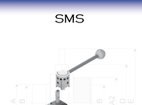
7. 7 S/S DIN 11850-2 F/F DIN M/G DIN S/S (altre dimensioni / other dimension) DN A B C D D1 G L L1 L2 Q Z Z A 40 41x1.5 58 82 124 124 65 508 584 556 100 33 26 40x1.5 50 53x1.5 52 82 124 124 59 508 584 556 110 35 28 52x1.5 65 70x2 60 98 146 148 68 557 647 610 120 40 32 80 85x2 68 113 146 169 75.5 572 677 625 130 45 37 100 104x2 81.5 145 150 178 83 675 818 725 150 54 44 125 129x2 124 195 194 248 124.5 779 973 850 150 46 34 150 154x2 112 195 194 248 112 779 973 850 150 50 37 B 935 B935 B935 doppio corpo/double body B935V barriera vapore/steam barrier DIMENSIONI mm DIMENSIONS mm LEGENDA / KEY S/S DIN Saldare / Welding F/F DIN Femmina / Male M/G DIN Maschio + girella / Liner + nut S/S DIN 11850/2 Saldare - Welding Din 11850/2 CLAMP Clamp F/F SMS Femmina / Male SMS F/F IDF Femmina / Male IDF F/F BS Femmina / Male BS Altre dimensioni su richiesta / Other dimensions on request S/S INCHES F/F SMS F/F IDF F/F BS DN A B C D D1 G L L1 L2 Q Z Z Z 1” 1/2 38.1x1.5 59 82 124 124 66 508 584 556 100 20 21.5 26.5 2” 50.8x1.5 53 82 124 124 59.5 508 585 556 110 20 21.5 26.5 2” 1/2 63.5x1.5 63 98 146 148 70.5 555 647 610 120 24 21.5 26.5 3” 76.1x2 73 113 146 169 80 570 680 625 130 24 21.5 26.5 4” 101.6x2 81.5 145 150 178 83 675 818 725 150 25 21.5 26.5 S/S ASME-BPE CLAMP DN A B C D D1 G L L1 L2 Q Z 1” 1/2 38.1x1.65 59 82 124 124 66 508 584 556 100 12.7 2” 50.8x1.65 53 82 124 124 59.5 508 585 556 110 12.7 2” 1/2 63.5x1.65 63 98 146 148 70.5 555 647 610 120 12.7 3” 76.2x1.65 73 113 146 169 80 570 680 625 130 12.7 4” 101.6x2.11 81.5 145 150 178 83 675 818 725 150 15.8 6” 152.4x2.77 - - - - - - - - - -