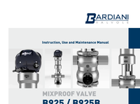
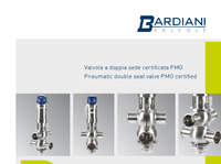
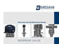
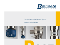
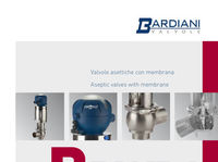
1. B 925 Valvole a doppia sede pneumatica Pneumatic double seat valves
3. 3 DATI TECNICI B 925 STRUTTURA VALVOLA Connessioni da DN15 a DN150 DIN, SMS, IDF, BS (RJT), Clamp, Flangia Altre connessioni a richiesta Materiale a contatto con il prodotto AISI 316L (1.4404) Altro materiale a richiesta Materiale guarnizioni a contatto con il prodotto (omologazione FDA, 3A) EPDM, FKM, HNBR. Omologazione EHEDG per EPDM. Altro materiale a richiesta Temperatura massima prodotto (EPDM applicazioni con aria) 140 °C (284 °F) Per temperature diverse contattare Bardiani Valvole Temperatura minima prodotto (EPDM applicazioni con aria) -10 °C (14 °F) Pressione massima prodotto 10 bar (145 psi) Pressione massima di tenuta 10 bar (145 psi) Finitura superficiale materiale a contatto con il prodotto Ra 0.8 μm (altri tipi di finitura a richiesta) Connessioni barriera vapore attacchi 1/8” (BSP) STRUTTURA ATTUATORE PNEUMATICO Attacchi aria 1/8” (BSP) per tubo 6 x 4 mm Pressione Da 6 bar (87 psi) a 8 bar (116 psi) 4.3 bar (62 psi) su richiesta Materiale cilindro AISI 304 (1.4301) Materiale guarnizioni NBR SI CONSIGLIA L’APPLICAZIONE IN VERTICALE VALVE STRUCTURE Connections from DN15 to DN150 DIN, SMS, IDF, BS (RJT), Clamp, Flange Other connections on request Material in contact with the product AISI 316L (1.4404) Other material on request Gasket material in contact with the product (homologation FDA, 3A) EPDM, FKM, HNBR. EHEDG homologation for EPDM. Other material on request Max. product temperature (EPDM applications with air) 140 °C (284 °F) For different temperature, please ask Bardiani Valvole Min. product temperature (EPDM applications with air) -10 °C (14 °F) Max. product pressure 10 bar (145 psi) Max. working pressure 10 bar (145 psi) Finish on surfaces in contact with the product Ra 0.8 μm (other types of surface finish on request). Connection steam barrier connectors 1/8” (BSP) PNEUMATIC ACTUATOR STUCTURE Air connectors 1/8” (BSP) for pipe 6 x 4 mm Air pressure From 6 bar (87 psi) to 8 bar (116 psi) 4.3 bar (62 psi) Cylinder material AISI 304 (1.4301) Gasket material NBR VERTICAL FITTING IS ADVISABLE TECHNICAL DETAILS B925 Deviatrice / Divert B925
8. 8 B 925 CONFIGURAZIONI CORPI VALVOLA VALVE BODIES CONFIGURATIONS CONFIGURAZIONI CORPI VALVOLA B925 CONFIGURAZIONI CORPI VALVOLA ORIENTABILI B925 CONFIGURAZIONI CORPI VALVOLA ORIENTABILI B925 1° - 2° - 3° .... esempi di lettura per attacchi con tipi e/o dimensioni diverse 1st - 2nd - 3rd .... examples for reading ends connections with different types and/or dimensions SENSO ORARIO CLOCK WISE Chiusa Aperta Closed Open Direzione fluido raccomandata Recommended flow direction 2° 1° 4° 1-0° LL 1-90° LL 1-180° LL 1-270° LL 2-0° LT 2-90° LT 3-0° TL 3-90° TL 4-0° TT 4-90° TT 1 “LL” 2 “LT” 3 “TL” 4 “TT” 5 “LLL” 6 “LLT” 7 “LTT” 8 “TTT” 9 “LTL” A “TLT” B “TTL” C “TLL” 2° 1° 3° 4° 6° 5° ORIENTABLE VALVE BODIES CONFIGURATIONS B925 ORIENTABLE VALVE BODIES CONFIGURATIONS B925 VALVE BODIES CONFIGURATIONS B925 Chiusa Aperta Closed Open Chiusa Aperta Closed Open 5 LT Femmina / Clamp / Saldare 5 LT Male / Clamp / Weld 3°
4. 4 B 925 SOLUZIONI VARIE DIFFERENT SOLUTIONS B 925V BARRIERA VAPORE Impiegata in applicazioni particolarmente delicate dove ste - rilità, asetticità o alte temperature di sterilizzazione sono necessarie. L’utilizzo di una barriera di vapore situata tra il corpo valvola e la parte pneumatica e posta sull’otturatore inferiore, consente di ottenere una sicura separazione fra prodotto all’interno della valvola ed ambiente esterno. B 925V STEAM BARRIER A steam barrier is recommended for very hygiene applications such as sterile, aseptic processing or high temperature sterilization. The steam barrier, placed between the valve body and the pneumatic actuator and placed on the lower shutter, allows safe separation between the product and the external atmosphere. IN CERTIFICAZIONI / CERTIFICATIONS TY PE EL MA Y 2008 A ( 1 : 2 ) 0.1 0.1 0.1 0.1 Materiale: Material: Disegno Drawing Tolleranze geometriche non indicate. Not indicate geometric tolerance. Descrizione 2/Description 2 Tolleranza diametri Diameter tolerance Tolleranza lunghezze Length tolerance Spigoli Edge Raggi non quotati Not dimensioned radius Smussi non quotati Not dimensioned chamfer ± 0.1 ± 0.1 R=0.4 0.4 0.5x45° DIT: N° Approvato da Approved by Questo disegno e le informazioni in esso contenute sono di prop rietà della BARDIANI VALVOLE. E’ vietata la copia e la riproduz ione anche parziale senza un regolare permesso scritto della BA RDIANI VALVOLE. This design and the information contained therein are copyright ed by Bardiani Valvole S.p.A. Copy or reproduction of the des ign, even if partial, is strictly forbidden without Bardiani Va lvole’s written consent. Descrizione 1/Description 1 Data Date Scala Scale Redatto da RTE: Designed by RTE: Codice: Code: 1:3 S. Pesci ARDIANI V A L V O L E A OUT
6. 6 B 925 SOLUZIONI VARIE DIFFERENT SOLUTIONS B 925A CIRCUITO AUSILIARIO DI LAVAGGIO + BARRIERA DI VAPORE L’utilizzo combinato del circuito esterno di lavaggio e della barriera di vapore rende le valvole B925 totalmente asettiche e perfettamente pulite. Infatti, il circuito ausiliario di lavaggio permette, tramite l’utilizzo di prodotti sanifican - ti, la completa pulizia degli otturatori telescopici delle valvole a doppia sede. Inoltre, l’utilizzo della barriera di vapore, posta tra il corpo valvola e la parte pneumatica e sull’otturatore inferiore, consente di ottenere una sicura se - parazione fra prodotto all’interno della valvola ed ambiente esterno. Questa configurazione è stata ideata con l’obiettivo di garantire la massima asetticità e sanificazione, salvaguardando comunque il perfetto funzionamento della valvola. B 925A AUXILIARY EXTERNAL CLEANING + STEAM BARRIER Combining an External CIP Port with a Steam Barrier, makes the B925 ranges of double seat valves totally aseptic and perfectly cleanable. The auxiliary cleaning system allows cleaning of the telescopic shutters and stems of the val - ves, while the steam barrier, placed between the valve body and the pneumatic actuator and on the lower shutter, avoids the mixing of the product and the external atmosphere. CERTIFICAZIONI / CERTIFICATIONS TY PE EL MA Y 2008 IN OUT CIP A ( 1 : 2 ) 0.1 0.1 0.1 0.1 Materiale: Material: Disegno Drawing Tolleranze geometriche non indicate. Not indicate geometric tolerance. Descrizione 2/Description 2 Tolleranza diametri Diameter tolerance Tolleranza lunghezze Length tolerance Spigoli Edge Raggi non quotati Not dimensioned radius Smussi non quotati Not dimensioned chamfer ± 0.1 ± 0.1 R=0.4 0.4 0.5x45° DIT: N° Approvato da Approved by Questo disegno e le informazioni in esso contenute sono di prop rietà della BARDIANI VALVOLE. E’ vietata la copia e la riproduz ione anche parziale senza un regolare permesso scritto della BA RDIANI VALVOLE. This design and the information contained therein are copyright ed by Bardiani Valvole S.p.A. Copy or reproduction of the des ign, even if partial, is strictly forbidden without Bardiani Va lvole’s written consent. Descrizione 1/Description 1 Data Date Scala Scale Redatto da RTE: Designed by RTE: Codice: Code: 1:3 S. Pesci ARDIANI V A L V O L E A
5. 5 CONNESSIONI DISPONIBILI AVAILABLE CONNECTIONS B 925 SOLUZIONI VARIE DIFFERENT SOLUTIONS B 925B CIRCUITO AUSILIARIO DI LAVAGGIO Indicata in tutte le applicazioni dove si voglia ottenere una sa - nificazione esterna. Il circuito ausiliario di lavaggio permette, grazie ad uno speciale inserto posto all’interno dell’otturato - re, di distribuire il fluido sanificante in modo omogeneo. Tale distribuzione avviene sottoforma di turbolenza, consentendo la completa rimozione di eventuali impurità dagli otturatori. B 925B AUXILIARY EXTERNAL CLEANING In automated double seat valves, especially where separate seat lifts are not available, an auxiliary external cleaning sy - stem will enable CIP fluids to clean the telescopic shutters and the valve stem. The cleaning operation can be performed either with the valve closed or opened. This device makes the valve very clean and hygienic. Maschio BSP 1/4” BSP 1/4” external threading Clamp 1/2” Clamp 1/2” Maschio M14x1,5 per tubo ø 8 M14x1.5 liner for pipe ø 8 CERTIFICAZIONI / CERTIFICATIONS TY PE EL MA Y 2008 CIP B ( 1 : 2 ) 0.1 0.1 0.1 0.1 Materiale: Material: Disegno Drawing Tolleranze geometriche non indicate. Not indicate geometric tolerance. Descrizione 2/Description 2 Tolleranza diametri Diameter tolerance Tolleranza lunghezze Length tolerance Spigoli Edge Raggi non quotati Not dimensioned radius Smussi non quotati Not dimensioned chamfer ± 0.1 ± 0.1 R=0.4 0.4 0.5x45° DIT: N° Approvato da Approved by Questo disegno e le informazioni in esso contenute sono di prop rietà della BARDIANI VALVOLE. E’ vietata la copia e la riproduz ione anche parziale senza un regolare permesso scritto della BA RDIANI VALVOLE. This design and the information contained therein are copyright ed by Bardiani Valvole S.p.A. Copy or reproduction of the des ign, even if partial, is strictly forbidden without Bardiani Va lvole’s written consent. Descrizione 1/Description 1 Data Date Scala Scale Redatto da RTE: Designed by RTE: Codice: Code: 1:4 S. Pesci ARDIANI V A L V O L E B
7. 7 SPECIAL OPTIONS AND VARIATION ON REQUEST On request most accessories are available for all sizes of val - ve and body configurations. Additionally special ports, diame - ters and other tailor-made solutions are available. Bardiani Valvole can also provide technical support, advice and feasi - bility analysis for other requests. AUXILIARY PROXIMITY The auxiliary proximity is fitted between the valve body and the actuator and guarantees the complete check of the upper shutter during the cleaning operation or in case there is a water hammer in the plant that could open the upper shutter. VALVE BODIES with different sizes It is possible to supply bodies with ports of a different diame - ter from the standard. JACKET BODY A heated body jacket is typically used to avoid the solidifica - tion of melted products. Hot water circulating in the jacket helps to maintain the temperature and product fluidity. It also helps to extend gasket life. Typically used on fats and waxes. CORPI VALVOLA di diverse dimensioni Per ogni diametro indicato nella tabella delle dimensioni, è possibile ottenere su richiesta corpi valvola con attacchi di diametro diverso. CAMICIA DI RISCALDAMENTO L’applicazione delle camicie di riscaldamento sui corpi valvo - la è particolarmente indicata per tutti i prodotti che tendono a solidificare. Questo accessorio tramite l’utilizzo di acqua surriscaldata determina per induzione una fluidità al prodot - to durante le fasi di lavorazione, evitando una precoce usura degli elastometri. ESECUZIONI SPECIALI SU RICHIESTA Ogni accessorio è disponibile su richiesta del cliente per tut - ti i diametri e tutte le configurazioni corpi valvola. È inoltre possibile la personalizzazione di attacchi, diametri oppure soluzioni non presenti a catalogo. Bardiani Valvole consiglia di consultare sempre l’ufficio tecnico in fase d’ordine per ul - teriori informazioni e studi di fattibilità. PROXIMITY AUSILIARIO L’applicazione di un proximity ausiliario posto tra parte pneu - matica e corpo valvola, garantisce il completo monitoraggio dell’otturatore superiore nelle fasi di apertura di lavaggio o nel caso si generasse un colpo d’ariete nell’impianto tale da produrre il sollevamento dell’otturatore superiore. B 925 SOLUZIONI VARIE DIFFERENT SOLUTIONS
2. 2 ESTREMA PULIZIA Sistema barriere vapore (opzionale) SICUREZZA Controllo lift superiore (opzionale) SICUREZZA Controllo lift inferiore (opzionale) ESTREMA PULIZIA Sistema di lavaggio ausiliario (opzionale) FORZA Corpo ricavato da massello pieno B 925 CERTIFICAZIONI / CERTIFICATIONS TY PE EL MA Y 2008 SAFETY Upper lift feedback indication (optional) SAFETY Lower lift feedback indication (optional) EXTREMELY CLEANING Steam barriers system (optional) EXTREMELY CLEANING Auxiliary CIP system (optional) STRENGTH Balanced shutter made from solid bar (standard) Great water hammer endurance STRENGTH Body made from solid bar FORZA Otturatori bilanciati ricavati da pieno (standard) Maggiore resistenza ai colpi d’ariete
9. 9 Prodotto Product CIP Prodotto Product Prodotto Product CIP Prodotto Product CIP B 925 FUNZIONAMENTO WORKING VALVOLA CHIUSA Il prodotto e il liquido di la - vaggio sono separati dagli otturatori. Eventuali perdi - te fuoriescono dal condotto dell’otturatore inferiore. VALVOLA APERTA (aria ingresso 1) L’otturatore inferiore scorre trascinando quello superiore e chiude l’accesso al condot - to di scarico, in questo modo si determina l’apertura della valvola. Durante questa fase non si verifica nessuna per - dita di prodotto, grazie alla tenuta radiale posta sull’ot - turatore inferiore. LAVAGGIO SEDE SUPERIORE (aria ingresso 2) L’azionamento parziale dell’ot - turatore superiore durante il ciclo di lavaggio del corpo, mediante una azione tempo - rizzata (corsa non regolabi - le) consente la pulizia della camera di separazione, sedi e condotto di scarico. LAVAGGIO SEDE INFERIORE (aria ingresso 3) L’azionamento parziale dell’ot - turatore inferiore durante il ciclo di lavaggio del corpo, mediante una azione tempo - rizzata (corsa non regolabi - le) consente la pulizia della camera di separazione, sedi e condotto di scarico. OPEN VALVE (inlet air 1) The lower plug lifts, pushing the upper one, and closes the access to the drainage duct, causing full opening of the valve. During this phase, the radial seal fitted in the lower plug gives a complete seal without any product le - akage. CLEANING OF UPPER SEAT (inlet air 2) During the body cleaning phase, partial lifting (not adjustable stroke) of the up - per plug allows the cleaning of the plugs, seats and drai - ning ducts, flowing through the leakage detector. CLEANING OF LOWER SEAT (inlet air 3) During the body cleaning phase, partial lifting of the lower plug (not adjustable stroke) allows the cleaning of the plugs, seats and drai - ning ducts. CLOSED VALVE The Product and the CIP are separated by the plugs, any leakage will flow out throu - gh the leakage duct, without contamination of the other line. Lavaggio sede superiore (aria ingresso 2) Upper lift (air to 2) Fig.3 Lavaggio sede inferiore (aria ingresso 3) Lower lift (air to 3) Fig.4 Valvola chiusa Closed valve Fig.1 Valvola aperta (aria ingresso 1) Operating valve (air to 1) Fig.2 1 3 2 1 3 2 1 3 2 1 3 2 Aria Air Aria Air Aria Air
11. 11 LEGENDA / KEY S/S DIN Saldare / Welding F/F DIN Femmina / Male M/G DIN Maschio + girella / Liner + nut S/S DIN 11850/2 Saldare - Welding Din 11850/2 CLAMP Clamp F/F SMS Femmina / Male SMS F/F IDF Femmina / Male IDF F/F BS Femmina / Male BS B 925 DIMENSIONI mm DIMENSIONS mm CONSUMI ARIA AIR CONSUMPTION Litri per pressione aria Litre for air pressure DN Apertura Opening Lift superiore Upper lift Lit inferiore Lower Lift 25 - 32 - 40 0.28 0.05 0.15 50 0.30 0.05 0.15 65 0.59 0.08 0.20 80 0.61 0.08 0.20 100 0.98 0.11 0.29 125 1.87 0.17 0.38 150 1.87 0.17 0.38 B925 B925 deviatrice/divert
12. I-CAT-B925-0719 Bardiani Valvole SpA - via G. di Vittorio, 50/52 - 43045 Fornovo di Taro (PR) - Italy tel. +39 0525 400044 - fax +39 0525 3408 - bardiani @ bardiani.com - www.bardiani.com RECOMMENDATIONS 1 Consultation of the “Instruction, Use and Maintenance Manual” is mandatory prior to the installation, use and maintenance of the products of all Products. All the information, indications, specifications, technical details provided herein are based on test data which the Manufacturer Bardiani Valvole S.p.A. holds to be reliable nevertheless the above is not deemed to be assumed as fully exhaustive inasmuch as not every possible use has been envisaged. 2 All the illustrations and drawings provided are to be intended as indicative and therefore not binding, the illustrations being for presentation purposes only. 3 It is the Buyer’s duty to assess the suitability of the Products for the use he intends to make of the same prior to placing the order as he/she will take the risks and accept liability in case of incorrect choice and use of the Products. 4 The Manufacturer strongly recommends the Buyer to contact their sales team and request any information that might be needed in relation to the specifications and uses of the Products. 5 The information provided in this manual refers to the standard products manufactured by Bardiani Valvole S.p.A. and therefore cannot be assumed to apply to customized products as well. 6 Bardiani Valvole S.p.A. reserves the right to amend and/ or integrate and/or update the data and/or information and/or technical details relative to Products at any time and without prior notice. Please visit the website www. bardiani.com , where the latest updated of the “Instruc - tion, Use and Maintenance Manual” can be found”. 7 The content and validity of the warranty covering the Products of Bardiani Valvole S.p.A are dealt with in the relevant section in the “Instruction, Use and Mainte - nance Manual” which constitutes an integral part of the Products themselves. 8 Bardiani Valvole S.p.A., shall not in any way be held liable for immaterial, indirect and consequential dam - ages, such as (by way of example only), damages or loss of business, contracts, opportunities, time, production, profits, goodwill, image etc.. RACCOMANDAZIONI 1 E’ obbligatoria la consultazione del Manuale di Is - truzioni, Uso e Manutenzione” prima di procedere all’installazione, all’utilizzo e alla manutenzione dei Prodotti. Tutte le informazioni, le indicazioni, le specifiche e le notizie tecniche qui riportate sono ba - sate su dati di prove che Bardiani Valvole S.p.A. ritiene attendibili, ma che non sono riferibili ad ogni possibile utilizzo del Prodotto. 2 Le raffigurazioni e i disegni, tutti di valore generale, indicativo e non vincolante, possono non corrispondere alle reali condizioni dei Prodotti. 3 Dal momento che le condizioni di uso e applicazione del Prodotto ed il suo utilizzo sono al di fuori del controllo di Bardiani Valvole S.p.A., l’Acquirente deve preven - tivamente accertare la sua idoneità all’uso al quale intende destinarlo e assume ogni conseguente rischio e responsabilità che ne deriva dall’uso stesso. 4 Si raccomanda all’Acquirente di consultare sempre i collaboratori tecnici-commerciali di Bardiani Valvole S.p.A. per richiedere informazioni specifiche in merito alle caratteristiche tecniche dei Prodotti. 5 Quanto riportato nel presente Manuale si riferisce a prodotti di standard di Bardiani Valvole S.p.A. e non può in nessun caso costituire un riferimento di base per prodotti realizzati su specifiche richieste. 6 Bardiani Valvole S.p.A. si riserva il diritto, senza obbligo alcuno di comunicazione, di modificare e/o integrare e/o aggiornare, in qualsiasi momento, i dati e/o le in - formazioni e/o le notizie tecniche relative ai Prodotti. Si invita alla consultazione del sito Internet www.bardiani. com nel quale è pubblicata l’ultima versione aggiornata del “Manuale di Istruzioni, Uso e Manutenzione”. 7 Il contenuto e la durata della garanzia dei prodotti di Bardiani Valvole S.p.A. sono disciplinati nella relativa sezione del “Manuale di Istruzioni, Uso e Manuten - zione” che costituisce parte integrante dei prodotti medesimi. 8 In nessun caso Bardiani Valvole S.p.A. sarà responsa - bile per danni immateriali, indiretti e consequenziali quali, a mero titolo di esempio, danni o perdite di attiv - ità, di contratti, di opportunità, di tempo, di produzione, di profitti, di avviamento, di immagine ecc..
10. 10 S/S DIN 11850-2 F/F DIN M/G DIN S/S (altre dimensioni / other dimension) DN A B C D L L1 Q Z Z A 15 19x1.5 84 60 124 588 648 60 21 17 20 23X1.5 86 60 124 588 648 60 24 18 25 29x1.5 96 70 124 615 685 90 29 22 29x1.5 32 35x1.5 99 70 124 615 685 90 32 25 35x1.5 40 41x1.5 102 70 124 615 685 90 33 26 41x1.5 50 53x1.5 113 82 124 644 726 110 35 28 53x1.5 65 70x2 128 98 146 713 811 120 40 32 80 85x2 142 113 146 750 863 130 45 37 100 104x2 165 145 169 902 1047 150 54 44 125 129x2 188 195 213 1063 1158 150 46 34 150 154x2 201 195 213 1063 1158 150 50 37 B 925 DIMENSIONI mm DIMENSIONS mm Altre dimensioni su richiesta / Other dimensions on request S/S INCHES F/F SMS F/F IDF F/F BS DN A B C D L L1 Q Z Z Z 1” 25.4x1.5 95 70 124 615 685 90 15 21.5 26.5 1” 1/2 38.1x1.5 101 70 124 615 685 90 20 21.5 26.5 2” 50.8x1.5 112 82 124 644 726 110 20 21.5 26.5 2” 1/2 63.5x1.5 125 98 146 713 811 120 24 21.5 26.5 3” 76.1x2 137 113 146 750 863 130 24 21.5 26.5 4” 101.6x2 165 145 169 902 1047 150 25 21.5 26.5 S/S ASME-BPE CLAMP DN A B C D L L1 Q Z 1” 25.4x1.65 95 70 124 615 685 90 12.7 1” 1/2 38.1x1.65 101 70 124 615 685 90 12.7 2” 50.8x1.65 112 82 124 644 726 110 12.7 2” 1/2 63.5x1.65 125 98 146 713 811 120 12.7 3” 76.2x1.65 137 113 146 750 863 130 12.7 4” 101.6x2.11 165 145 169 902 1047 150 15.8 6” 152.4x2.77 - - - - - - -